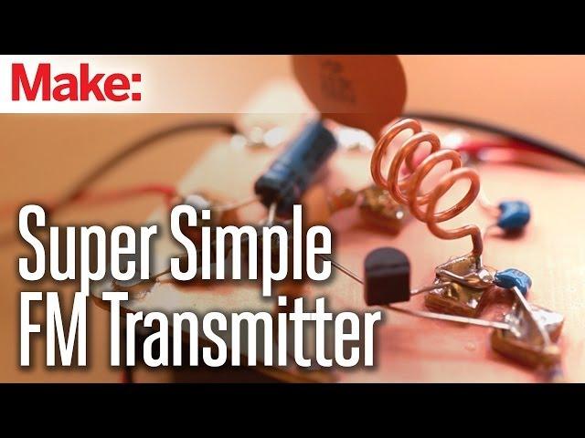
Weekend Projects - Super Simple FM Transmitter
Комментарии:

No cct diagram, its amzing but not for mew commer
Ответить
That's a blast from the past. My last local Radio Shack closed down several years ago.
Ответить
Excellent! Precise! Thorough! My Middle school kids could follow this.
Ответить
Please I need already develop transister . How can I get from u sir.
Ответить
Need a license never negotiate with terrorists On behalf of the entire planet suck my balls government
Ответить
So where are the explanations ? You talk about understanding in the beggining, but then you just give instruction on mounting without any explanation
Ответить
Nice projek 👏
Ответить
Does anyone have any information on how this produces radio waves?
Ответить
Saya sangat tertarik dengan dunia RF terutama yang berkaitan dengan pemancar fm
Ответить
As a geeky kid almost 50 years ago I made this on my 100-in-1 radio shack kit. It worked so well and the audio quality was very good at over 100 feet away (with small antenna wire). I did not understand and still don't how the audio modulation worked on FM, since I thought I was making AM (amplitude modulation). Ah, radio shack. :>( 73 AB2ES
Ответить
Thank you so much. I truly appreciated your thoughtful video.
Ответить
I don’t have a radio shack
Ответить
Oh shit this video is 8 yrs old??? 😲 What a quality
Ответить
Can you not give the circuit diagram ?
Ответить
Would this circuit work to send signals from a laptop to a robot or some other gadget
Ответить
I've tried it four times and still cant get it to work, i used an "equivalent transistor" the bc547 is this my problem?
Ответить
Radio shack is out of business this must be in an old video
Ответить
Thankyou soo much sir .
Ответить
20 years ago I purchased an FM transmitter for some several hundred dollars. It was 130 Watt and covered a good radius. We were running pirate radio at the time. I opened it up and noticed it was a copper board with lots of hand soldered through-hole components. To this day I've always wanted to rebuild that and it's what got me started in electronics all those years ago. It looked very much like this, but larger, and there were some amps etc in there too. Very interesting stuff.
Ответить
Why doesnt it need a crystal oscilator?
Ответить
what type of transistor please?
Ответить
How can i make it with 5v power supply
Ответить
can we use fm radio on mobile to recieve this? please reply at the earliest!
Ответить
OK, built it. I had zero electronic experience before this, but ordered the parts, followed the directions on the video to the letter, powered it up......and.......IT WORKS!!!
I goofed up a couple of things, but I can correct those. It's broadcasting on 105.3 FM. It only has a range of a few feet, so I'm going to add an antenna and see if I can get it to broadcast 15-20 feet. Took me a grand total of about 3 hours, but I had a blast building it. Thanks for this most excellent video!

How can i do this qithout using the copper plate? I have perf board?!
Ответить
Saw dude taking about buying the parts at radio shack then saw that this vid is 9 years old lmao
Ответить
Actually it was quite new beside another was internet™
Ответить
In the other hand internet simply free
Ответить
Sebutannya seharga Radio FM
Ответить
Sebenarnya bukan tutup
Ответить
Makes a bluetooth
Ответить
Radio shack😢
Ответить
What is the frequency to scan in the FM reciever?
Ответить
What was that for transistor please?
Ответить
Hi can we boost the range of antenna of this by using a single transistor and some small components? Hihi
Ответить
Good job 😅😅
Ответить
Sir your experiment is very fantastic, but ould you please kindly tell me which transistor have you used in it?? Please kindly give a reply sir please
Ответить
How do you set a specific fm channel, say 107.5 or so?
Ответить
Guys, I made a 300THz oscillator from a diode which I get from an old remote control!!!
Ответить
at what frequency and band will it be broadcasted exactly? can i use a potentiometer or variable resistor to a different frequency
Ответить
How is this helpful or interesting even? I'd may as well just buy a transmitter if you aren't going to explain how it works and why the components need to be these specific values and dimensions..?
Ответить
Would you mind dropping the circuit diagram for this design
Ответить
Remember to wash your hands after soldering with lead-tin solder!
Ответить
Where is the schematic??
Ответить
didn't even show it working?‽
Ответить
If you don’t mind, show the diagram
Ответить
Hey, to any more knowledgeable electrical/RF engineers in the comments: how is this supposed to work?? I see what looks like an LC tank circuit (which is proved by a few other comments) and I assume that's how the base frequency is created, but then the audio input would have to be mixed onto the LC signal, and the only non-linear component here is the amplifier transistor. I assume there is no mixing stage and instead the audio signal is used to modify the resonance frequency of the LC tank, but I've never heard of any such magic.
Ответить
Literally explains nothing about how it worked, useless video, made me dumber...😢
Ответить


![[청주MBC뉴스] 대청호 쓰레기 제거 비상 [청주MBC뉴스] 대청호 쓰레기 제거 비상](https://hdtube.cc/img/upload/UVdwb0JNUE8zdVQ.jpg)


