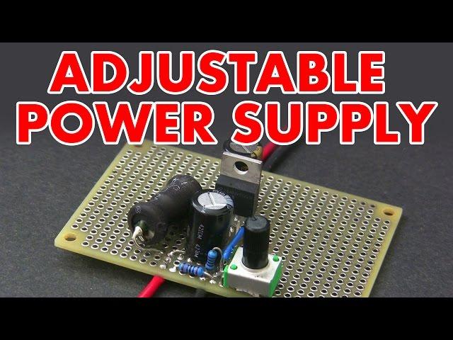
Adjustable switch mode power supply tutorial
Комментарии:

hi,i have a constant 15v dc power source,and i want to use pwm signal to control the buck converter,then i need the controllable output voltage.add the pwm signal on FB pin? and how to do that?
Ответить
can you please tell me the difference between this PWM and the one you made with an NE555 ?
Ответить
I like your turtorials
Ответить
hello is it neccesary to put a diode in the output so that the battery wont flow back to the circuit?
Ответить
Great video! I have a question. Can we just use potentiometer as voltage divider? Why use voltage divider AND pot? If no, please tell me why. Thanks :)
Ответить
Can anything be added t this to limit the max current at the output thus making an adjustable cc supply?thanks in advance.
Ответить
nice video bro . thanks . but what is the input and max output voltage ?
Ответить
So I can make a 12V-1.5V output out of 15VDC?
Ответить
Theoretically, couldn't you have the switching power supply at about the voltage you want and then run it through a linear voltage regulator to get a smooth D.C. Voltage with minimal heat on the linear voltage regulator? You would probably need a pot that is like a DPDT switch where you basically have 2 separate pots controlled by one knob to control the voltage output of the switching power supply and the linear regulator.
Ответить
Awesome video! Do you have a circuit for constant current control? It'd be super handy for driving LED's as well as over current protecting for testing prototype circuits.etc
Ответить
I'd like to build a 50W AC to DC transformer.
What do you recomend?

Would a shielded inductor help with the interference?
Ответить
I remember something. Now I know why my laptop charger can cause interference with my FM radio.
Ответить
Do I need the exact parts he used?
I tried building this, but I get 0V on the output.
I powered the circuit with a lab power supply, and it shows that the circuit draws 300mA.
Please, help!

Is there such circuit for 10 or more amps, or is it possible to add powerful FET to increase output current?
Ответить
wouldnt you need a flux capacitor for that? 😁... subscribed
Ответить
Excellent video, good advice just using the switcher chip. Keep 'em coming.
Ответить
Very good video, i have been looking for an explanation on that for a long time, and i'm really glad i found yours
Ответить
Why do you use 1k resistor after potentiometer? You said that if you connect it straight, it will output 1.21V, so why 'limit it' to minimum 2.5V?
Ответить
can i load a smartphones lithium ionen akku with it, or is it a bad idea (no current limitation)?
Ответить
Is Arnie doing electronics now?
Ответить
1.21 Giga Watts..
Ответить
Hi
Plz can u make a current regulator. To deliver stable current to drive of led or other loads with precise controlled currents

If the signal from the feedback voltage divider was sent to an Arduino Uno analog input and an output mapped to this signal sent back to the feedback pin of the LM2678T , would the Arduino be able to control the voltage output? Asking because I have no clue.
Ответить
Can you explain bootstrap configuration please
Ответить
That reference from Back to the Future, awesome hahaha
Ответить
if my loas isn't grounded, do i still need the divider?
Ответить
Cool video. How can this be adapted for very high currents to charge very big batteries?
Ответить
You really saved my day after i heared the Linear Voltage regulators are not very efficient, unless you want to heat your whole room. At first i was very irritated what component values i should use, but you explained the Voltage Divider very well, thank you very much 👍
Ответить
Very interesting video :) but, I've a question. How can i control this circuit with an Microcontroller (Aka Arduino)? I was thinking to use digital potentiometer but this isn't a good idea because they have few steps. Thank you :)
Ответить
soz but with socket input you can make anythink
Ответить
I thought I would never understand the function of electronic components. Thanks to your channel. You put things in simple words, in witch I could understand & not sound like my class instructor speaking in a foreign-language. Thank you
Ответить
one point twentyone gigawats - ha ha (back to the future), ofcourse with a lightningbolt what else.
Ответить
Hello, i want to design an SMPS with 5v USB input and dual output of 12v and 5V for Battery and Ardunio respectively. I would request you to suggest a PCB board or an IC.
Thanks and Regards

So the variable resistor is controlling the transistor
Ответить
So basically I can make an opamp add 1.20 volts to the output of the lm2678 to make it generate 0.01 volts? Hmmmm....
Ответить
can be a similar circuit with a LM2679?? I would like to use it because give more current in the output
Ответить
Very informative Thanks (y)
Ответить
hi good day..can i use a 3.7v battery for the input?
Ответить
Nicely done!
Ответить
This is a super solid tutorial, thank you so much!!!
Ответить
Really awesome video, especially going into detail about the EMI stuff
Ответить
The way you explained the voltage feedback comparison process for regulation in the dc-dc ic is simply art. The art of explaining complexity so well that it suddenly becomes simple things in cooperation. Great video.
Ответить
This video is excellent and it was made 9 years ago... I liked that 1.21GWatts reference xD
Ответить
Great 🎉
Ответить
wait , so we do not use the 3rd terminal of the potentiometer ? Do we ground it or what do we do
Ответить
Great explanation!
Ответить
this is awesome . finally i get it. thankss
Ответить


