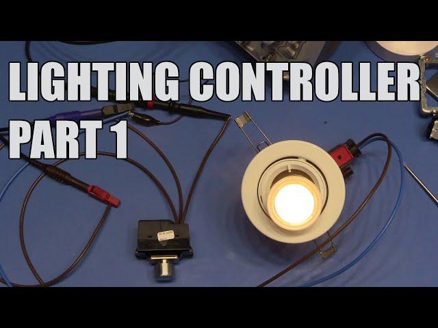
SDG #055 Testing AC Dimmer Modules - Lighting Controller Project - Part 1
Комментарии:

Yet again I did watch to the end, interesting stuff. I have a more mechanical way to operate my bed side lamp, efficiency is quite good. I find just a few sips of tea provides all the power required to simply extend my 5 digit hand together with a little help from my main processor, I can on a good day, manage to switch the light off. Local dimming is provided by changing the aperture of my vision detector circuit. My version does not require a PCB or any involvement from EBay.
Ответить
Thanks Steve. You don't make your own boards?
Ответить
For the input, copy DALI+Push button schematics. It is simple current limit for optocoupler with 2 bipolar transistors. One of them should be a high voltage one. This means nothing gets blown up, if you accidentally connect switches to the mains few years down the road or just connect to mains from the start :-)
I personally would never connect LEDs to a triac/mosfet mains dimmer. They were perfect for incandescent lamps,but they really stress power supplies and you never know if it is going to work or not and how long. You can get a "Push Button" LED power supply for cheap nowadays and you connect as many switches in parallel as you want. If you want to build a master controller then supplies with 1-10V input are even cheaper.
If you already have the luminaries with the socket then it is a bit more complicated, but there are some workarounds.

:popcorn: waiting for next video
Ответить
Very thorough Steve, thanks mate.
Ответить
IKEA smart lighting is good alternative
Ответить
You may be interested in the HT0440, it's pretty slow, but its probably fast enough for mains dimming, AN-D26 has some information that may be useful.
Ответить
Do those MK switches have a minimum wetting current? A cursory glance over their specs hasn't answered my question. Perhaps the contact material (brass?) is such that it doesn't matter.
Wetting current is one thing I double-check in my own designs. Cheers, R

Why not do multiple turns through the current clamp? Sometimes I’ll wrap a wire through my clamps 5-10 times to increase its sensitivity.
Though, I’m not sure if that would alter readings on clamps that are not Hall effect based

I don’t know if I’m more impressed that your making your own controller, or that you have MK Grid in your home, I love that system
Ответить
Let me tell you, I have some experience writing firmware both in consumer and aerospace but I never really designed for AC and mains. This was really interesting to watch.
Ответить
Great stuff Steve! Snap! Only just found this series, after having gone through a similar though process then designed and built pretty the exact same thing! I am still on a prototype board and not yet on a PCB.
Couple of quick questions:
1. R1=10k. That's huge. I have only a few Ohms. Admittedly, I am using 600V 27A Ron=0.1Ohm MOSFETS (gate charge 54nC) and a 2.5A driver because I wanted to be able to switch full mains power. So clearly I will need to pump in more charge quickly. But 10K still strikes me as very large for a power MOSFET gate. The calcs for these are really hard with lots of unknowns, so she rule of thumb I use is: "guess a value then look at the waveform with the scope and lower the resistance until you get ringing, then back off a bit."
2. I want to be able to switch inductive loads and I can't see how to make this kind of back-to-back MOSFET circuit allow freewheeling for the latter half of the cycle. The only thing I can think of is to add an additonal "freewheel MOSFET pair" directly across the load, which is carefully triggered only to be on when the main pair is off. It's a pain though because it needs yet another isolated gate drive supply, because the "joined sources" are at a different level. Better ideas?
I would be keen to get in touch to exchange ideas. Any comms channel you prefer.

With regard to wiring picking up transients, why not have either a capacitor across the input or an inductor (or even a ferrite bead or similar) inline with it? Or both? And, with that dual-MOSFET setup, are you relying on the body diodes to conduct for the one that isn't turned on? I've read that this isn't necessarily a good idea...
Ответить


