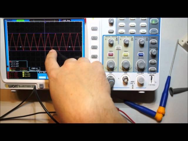
Inexpensive amazon LED Lighting Dimmer teardown and analysis
Комментарии:

Very interesting!
Ответить
Indeed quite interesting small device. Seems like a pretty easy conversion. Second LDO at the input (to like 24V or something) and replace the MOSFET with a 60V device. Job dobe :)
Ответить
yeah, just yesterday i was wondering when you were going to upload something agian. ;D
Ответить
Yep. I'm prolly going to swap the regulator so the 555 and op-amp run on 12V, so I can use a generic FET, rather then the logic-level FET currently on the board, though.
Ответить
I have a whole pile of stuff to upload, it just needs a bit of editing, and I'm laaaaazy. Basically, when I feel like doing something that takes effort, I tend to clock-in and do actual work for which I get paid. Other then that, I tend to just want to veg.
Ответить
Also, Windows Live Movie Maker kinda sucks, and iMovie takes like 6 hours to export a 30 minute video.
Ответить
A series resistor at the input of a potential regulator is to reduce the power dissipation in the regulator at high operating potentials across the regulator. I have an inverter that does this for its USB output, except that uses a >3W 10ohm (IIRC) resistor and a TO-220 7805 regulator.
Ответить
I didn't really think about that, but the math doesn't really work. The electronics in the dimmer draw ~0.008A (8 mA)! As such, a 200Ω resistor will only drop 1.6V. Anyways, the regulator is in a much better package for power dissipation (it has a power-tab).
Ответить
The total dissipation the the regulator (even with no resistor) would only be ~60 mW. Plus, 1206 is pretty terrible for power-dissipation.
Ответить
Note: The 78L05 is a SOT-89 package. I finally found the package info.
Ответить
This might be a PCB that is used for versions of this dimmer that operate at potentials above the maximum input potential rating of the regulator, in which case the resistor is simply to keep the regulator from popping. As this is Who Flung Dung Chicom stuff, the resistor is probably cheaper than using a higher input potential regulator. In this case, the resistor is just filler. That is the only other thing that I can think of.
Ответить
While true, it's *extremely* unlikely that even the Chinese would bother counterfeiting these ICs. The NE555 from TI is $0.55 each in single quantities, $0.10080 in 2.5K quants The LM358 from TI is also $0.55 each in single quantities, $0.10080 in 2.5K quants. Considering how cheap the ICs are (and this is from american distributors), it wouldn't be cost-effective to counterfeit. The devices you generally see knock-offs of are high-budget ICs.
Ответить
I have a POS CR123A cell charger, and the LM358 in the charging circuit has a logo that is designed to look like the Fairchild F, so dubious ones do exist. Also, yes, this charger uses just an operational amplifier for charge management of LITHIUM cells.
Ответить
That's what I thought too, but as Connor says the regulator isn't really being pushed. Capacitor charging inrush is the only other thing that comes to mind. Given how little current the circuitry uses they could have used a resistor and zener.
Ответить
Have you seen the 12V 3 channel RGB dimmers on ebay? They have three knobs to control the 3 channels and I opened it thinking it was just going to be three simple PWM circuits like this dimmer. But instead it used a microcontroller converting three analogue inputs from the pots to three channels of PWM.
Ответить
It is probably for 48V versions of this, as most cheap linear regulators max out at 37V or so. As the circuit operating current is fairly constant, all you need is a resistor that drops about 18V to 35V or so so that the regulator never sees more than 30 odd volts.
Ответить
What are the resistances on the stock resistors used in the 555 astable circuit? I'd love to know for predicting my timing with a simple cap change. Thanks
Ответить
Thanks, I needed to see what it would look like on a scope before I could buy it!
Ответить
The sound was horrible. Where was the microphone?
Ответить


